Introduction
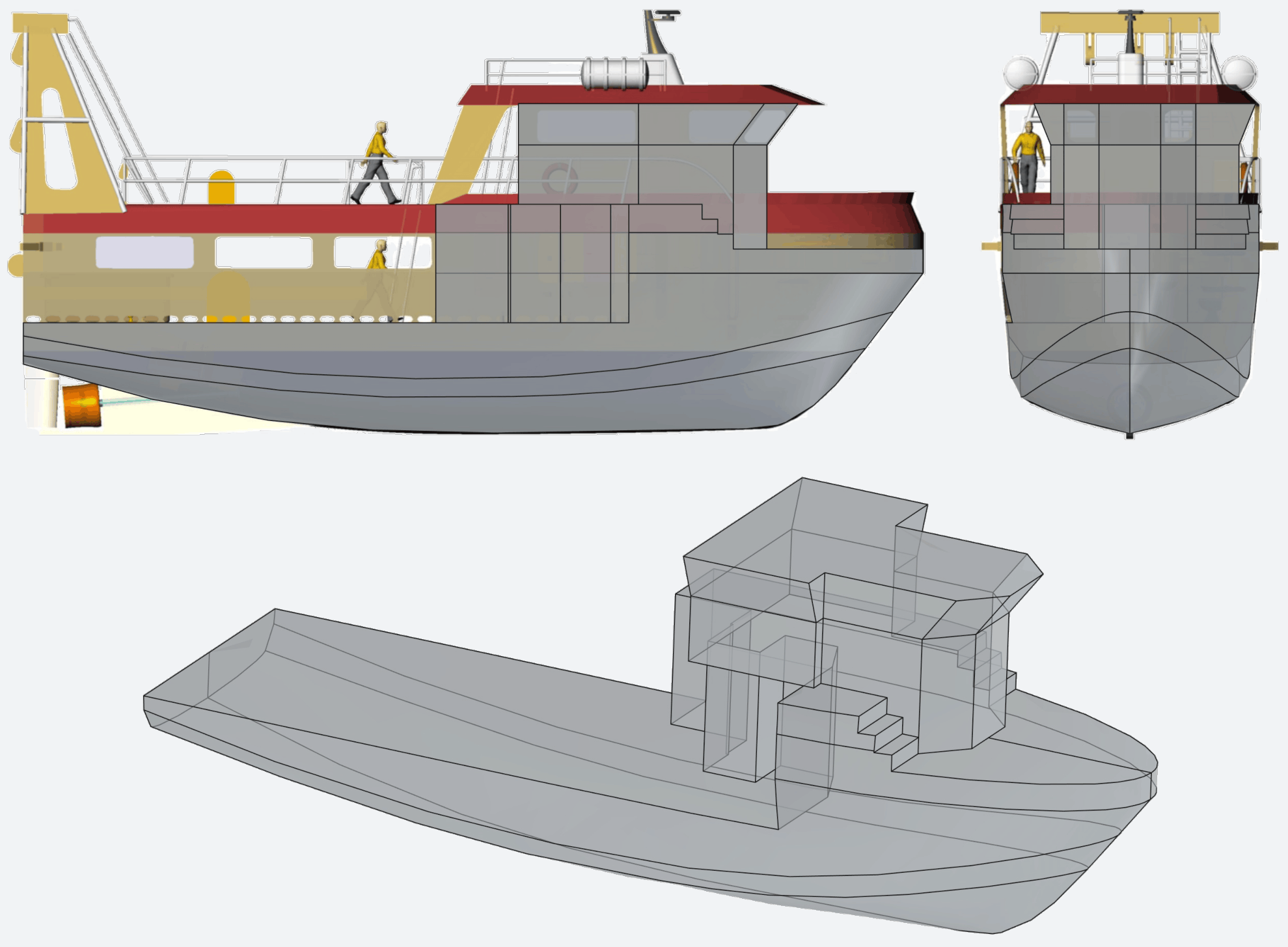
In this post is presented a basic intact stability analysis of a fishing vessel, which modeling was described in the last article. The vessel geometry is built with FreeCAD and the stability calculations are performed by NavalToolbox. The results are checked against the International Code on Intact Stability.
Methods
The analysis starts at the CAD modeling stage, to correctly determine what geometrical features can contribute to the vessel’s stability. The next step is estimating the vessel’s mass properties: displacement and center of gravity. Then, the geometry and mass properties are used by a specialized software to get basic hydrostatic properties and perform the actual intact stability analysis, which results are validated (or not) by criteria defined in international rules.
3D modeling
The surface that was modeled in the previous post has to be modified and incremented in order to get all the geometrical features that can contribute to the ship’s buoyancy. First, that surface is cut along the main deck level. Next, cabins, forecastle and wheelhouse are added. The final elements that make up all the enclosed volumes are presented in the following image.
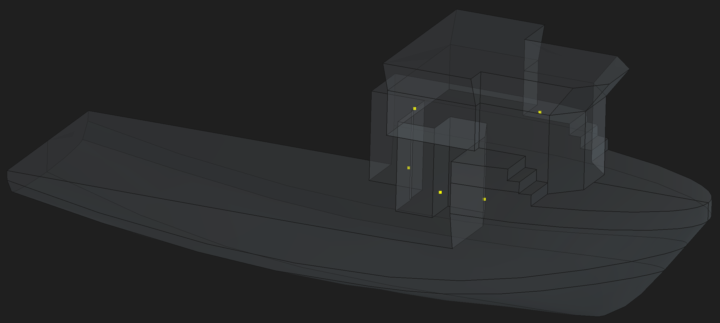
The doors that give access to the cabins and wheelhouse are not watertight, therefore, their sills must be identified as downflooding points. The next image shows these points as yellow dots.
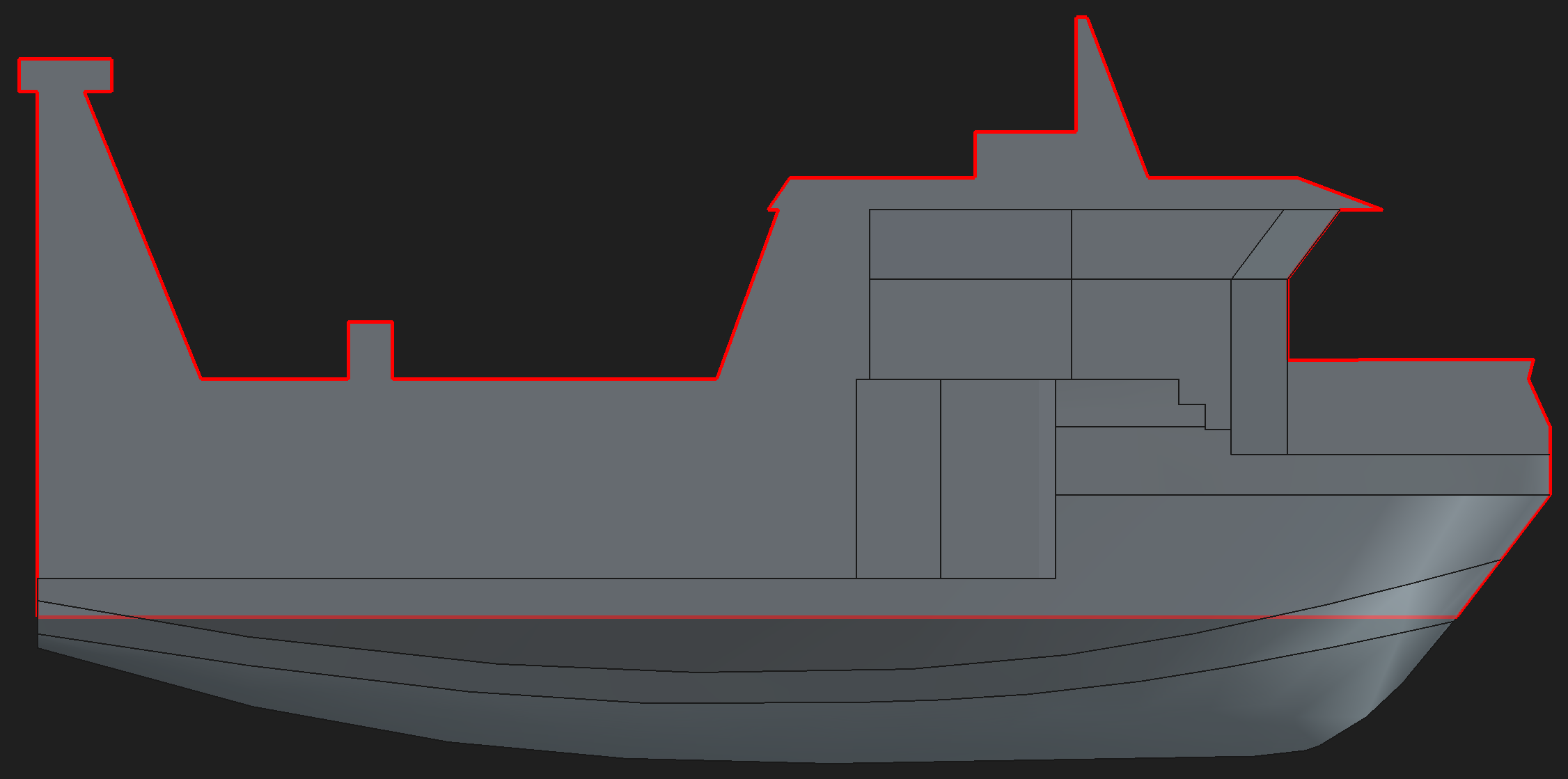
Another important aspect of the ship is its windage, which consists of the projected area of the vessel that is exposed to the wind. This area is represented by the red silhouette drawn in the next figure. The points that define this red boundary are exported in a csv file to be used by the stability software.
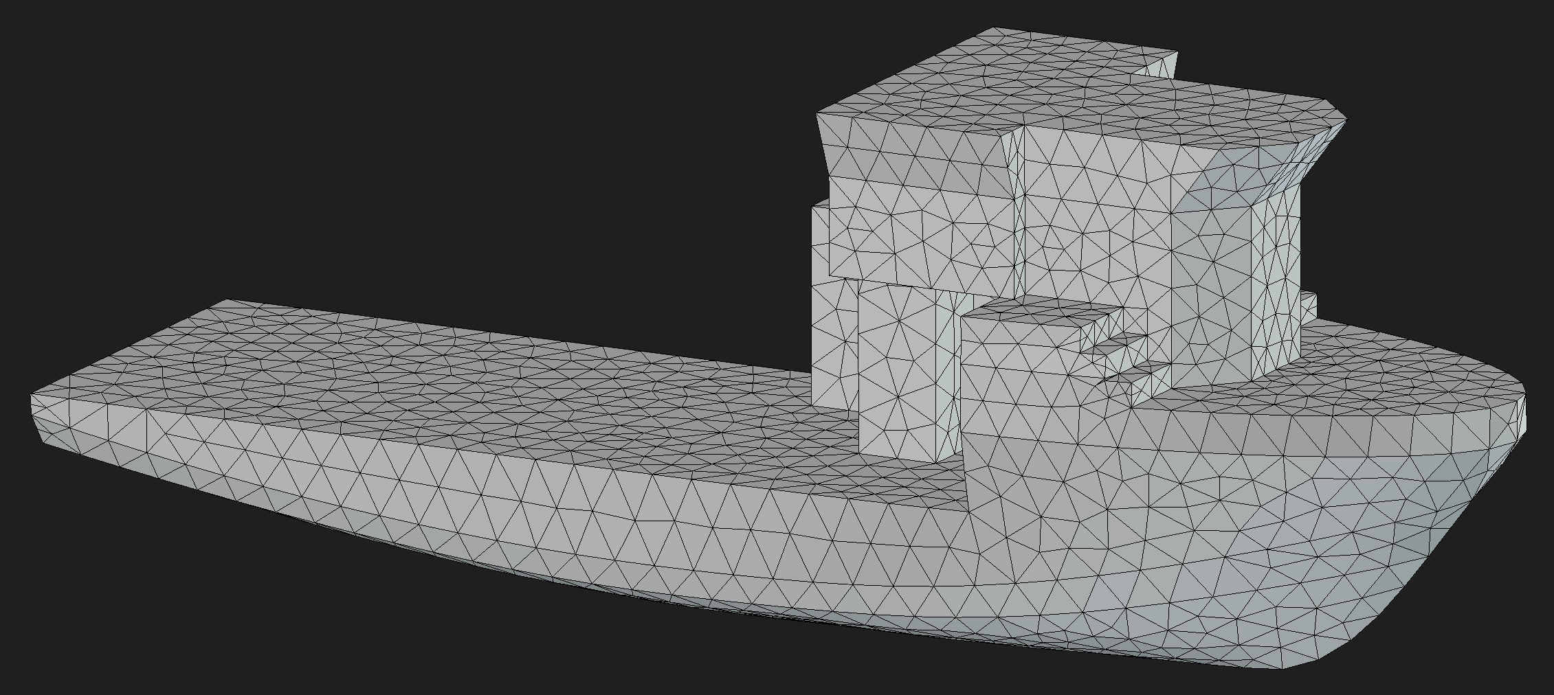
The geometry that represents the enclosed volumes of the vessel must be given to the stability software as a stl mesh. Thankfully, FreeCAD has Gmsh and other meshing tools integrated, which easily allowed the creation of the following mesh, containing 3602 faces.
Estimation of mass properties
The ship is studied at its design water level, therefore, displacement and longitudinal position of the center of gravity (LCG) can be easily obtained with NavalToolbox’s HydrostaticCalculator. No initial trim or list is assumed, so LCG = LCB (longitudinal center of buoyancy), and the transversal center of gravity (TCG) is zero. The remaining of the task is estimaing the vertical position of the center of gravity (KG). For this, we use the work of Kim & Yeo (2020). In this reference, the KG can be calculated as a function of the gross tonnage, for multiple loading conditions typical of fishing vessels. In the present article, it is assumed that the design waterline coincides with what Kim & Yeo define as “Fishing ground departure”, which configures the condition where the ship is fully loaded with fish and 75% of the consumables such as fuel, fresh water and provisions are already used. This is also the heaviest loading condition.
There is one caveat to this estimation process. When reading the article of Kim & Yeo, it’s noticeable, and verifiable by simple calculations, that the volumes occupied by cabins and wheelhouses are not included in the gross tonnage of the fishing vessels used as reference in their work. For this reason, the present work considers as enclosed volume, for the purpose of gross tonnage calculation, only the volume of the hull below the main deck level.
Intact stability analysis
The intact stability analysis is done with NavalToolbox, a free and open source library written in Rust, and with a Python API.
The analysis starts with the input of the geometry of vessel and its mass properties, both defined in the previous subtopics. Special attention is given to the downflooding points. The software has a tool that determines if a downflooding point is submerged or not for a chosen hydrostatic condition. However, it was noted that this tool does not always return the correct result, which can be double checked with the software’s visualization feature. Therefore, the maximum angle of heel that keeps the downflooding points emerged is verified manually, by taking the 3D visualization as the representative of the correct hydrostatic condition. The maximum angle of heel that will be taken by the vessel in the stability analysis is 50° to starboard, which is the larger angle accepted by the weather criterion. The following picture depicts the vessel in the mentioned condition, with the downflooding points marked as red dots.
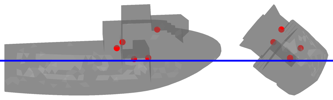
Despite some of the points being very close to the water surface, none of them is submerged. The choice of doing this checking only to starboard is due to the lower restoring arm when heeling to this direction, information which will be confirmed in the results section.
After all the input data is prepared, and the stability analysis is performed by NavalToolbox, the results are provided as input for the verification against the International Code on Intact Stability (2008). This checking is done by NavalToolbox built-in scripting engine based on Rhai. With the script, two sections of the international code are verified:
- 2.2 Criteria regarding righting lever curve properties
- 2.3 Severe wind and rolling critetion (weather criterion)
Results
The first result is shown in the next image. It consists of the GZ curve for the vessel heeling from -180° (port direction) to 180° (starboard direction). It clearly shows the impact of the vessel’s asymmetry in the righting lever.

The next picture displays the same result, but in a way that is easier to compare the value of the GZ when heeling to port or starboard. Clearly, the vessel is less stable when heeling to starboard. Therefore, the verification against the international rules considers only the vessel heeling to the less stable side.

The following image shows the parameters considered by the section 2.3 of the international code. The results of the actual checking performed by NavalToolbox are presented next.

2.2.1 Area 0-30    = 0.144 m⋅rad (reference value = 0.055 m⋅rad) → PASS
2.2.1 Area 0-40    = 0.221 m⋅rad (reference value = 0.090 m⋅rad) → PASS
2.2.1 Area 30-40   = 0.078 m⋅rad (reference value = 0.030 m⋅rad) → PASS
2.2.2 Min GZ Value = 0.427 m     (reference value = 0.200 m)     → PASS
2.2.3 Max GZ Angle = 50.000 °    (reference value = 25.000 °)    → PASS
2.2.4 GM0          = 1.298 m     (reference value = 0.150 m)     → PASS
2.3.1 Equilibrium  = 6.283 °     (reference value = 16.000 °)    → PASS
2.3.1 Weather      = 0.134 m⋅rad (reference value = 0.121 m⋅rad) → PASS
All the eight criteria verified passed! It’s important to note that the International Code on Intact Stability only applies to vessels of 24 meters in length and above. So the fishing vessel studied in this article doesn’t have to comply with the international rules, but it’s proven to abide by the minimum stability criteria adopted worldwide, at least for the studied loading condition.
Conclusion
This post was a nice presentation of important aspects that must be taken in a ship intact stability analysis: enclosed volumes, mass properties and statutory rules. However, what was presented is just a small part of a full study on ship stability. We didn’t convered tanks, multiple loading conditions or damage stability. Hopefuly these topics will be studied in future articles.
References
- Food and Agriculture Organization. 2026. Fishing Vessel Design Database - Trawler - 17.5m. https://www.fao.org/fishery/en/vesseldesign/mar-17
- Dong Jin Kim, Dong Jin Yeo. 2020. Estimation of drafts and metacentric heights of small fishing vessels according to loading conditions. International Journal of Naval Architecture and Ocean Engineering 12 (2020), 199–212. https://doi.org/10.1016/j.ijnaoe.2019.11.001
- Antoine Anceau. 2026. NavalToolbox Version 0.9.0. https://github.com/NavalToolbox/navaltoolbox-lib.
- International Maritime Organization. 2008. International Code on Intact Stability. International Maritime Organization, London.